Home › Unlabelled ›
Xlr Connector Wiring Diagram - Can Someone Please Confirm The Wiring For Hifiman Sundaras Balanced To Xlr Headphone Reviews And Discussion Head Fi Org / It shows the components of the circuit as simplified shapes, and the capability and signal links amongst the devices.
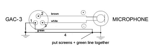
Xlr Connector Wiring Diagram - Can Someone Please Confirm The Wiring For Hifiman Sundaras Balanced To Xlr Headphone Reviews And Discussion Head Fi Org / It shows the components of the circuit as simplified shapes, and the capability and signal links amongst the devices.. But, it does not imply connection. This is correct assuming that the cable used is a two wire (1 conductor and 1 shield) cable. Introduction the xlr connector series is probably together with the speakon series neutrik's most known product range and has been due to the simple attractive front end design. Well, you might have to practice this a few times, but it's not as impossible as you might think. Being circular in design, these connectors consist of anything between 3 to 7 pins.
But, it does not imply connection. The xlr pinout for 3 pin xlr connectors is very standard. The dmx specification allows for two completely separate data channels over the one 5 pin connector. Pin 1 one bridged to the chasis). This is the wiring guide for the pad.
Lr 3121 Microphone Cable Wiring 3 Pin Xlr Wiring Diagram Toffercom Schematic Wiring from static-cdn.imageservice.cloud And also only when working with high level signals. Microphone electrical cable xlr connector phone connector audio and video interfaces and connectors, wires, electronics, cable png. The dmx specification allows for two completely separate data channels over the one 5 pin connector. Professional video connectors are crimped. Seven way trailer plug diagram. In the 60s a series of connectors for boeing planes was developed. In the pictures, you'll see a view of the xlr connector from the rear along take a look at the provided circuit diagram. This scheme can be adapted for dmx.
Being circular in design, these connectors consist of anything between 3 to 7 pins.
6 pin to 7 pin trailer wiring diagram. But there's one professional connector that is still soldered, the venerable xlr. Professional video connectors are crimped. Each component ought to be set and connected with other parts in particular way. Well, you might have to practice this a few times, but it's not as impossible as you might think. An xlr connector is a type of electrical connector which is mainly found on different types of audio, video, as well as stage lighting equipment at present. Pin 1 one bridged to the chasis). Headphones xlr connector headset microphone telex, earphone, electronics, microphone, electronic device png. In the pictures, you'll see a view of the xlr connector from the rear along take a look at the provided circuit diagram. Saves rack space by combining 2 connectors in one housing. There are switchcraft, cannon and canon connectors. Do not connect power to the touch panel until the wiring is complete. Horizontal or vertical pcb mounting or hard wire soldering.
The dmx specification allows for two completely separate data channels over the one 5 pin connector. In the diagram below, i show a possible wiring diagram that also takes into consideration the split pair wiring that a properly built rj45 ethernet cable needs to follow. Requested video for wiring a xlr to rca cable.using only microphone connectors and rca tags: Each component ought to be set and connected with other parts in particular way. An xlr connector is a connector that is widely used in the sphere of professional lighting and audio mastering.
Xlr Connector Rca Connector Wiring Diagram Electrical Wires Cable Taxi Meter Angle Electronics Png Pngegg from e7.pngegg.com But, it does not imply connection. February 24, 2019february 23, 2019. Mini xlr wiring diagram 5 pin connector wire for din wiring diagram led 4 pin schematic xlr cable schematic wiring diagram soldering audio 107 rgr ham radio mic wiring diagrams diagram 5 pin xlr connector wiring diagram schematics. This video explains how to solder xlr to trs connector with detailed connection diagrams. All wiring diagrams i have seen do not seem to show this (i.e. Being circular in design, these connectors consist of anything between 3 to 7 pins. If not, the structure won't function as it should. Well, you might have to practice this a few times, but it's not as impossible as you might think.
If not, the structure won't function as it should.
The easiest way is to solder a link between pins 1 and 3 (shield and negative) of the xlr, rather than trying to solder the shield and negative wire to the sleeve contact of. The dmx specification allows for two completely separate data channels over the one 5 pin connector. Another well used convention can be found on many cameras, where pin 1 is 0v and pin 4 +12v, others not connected. And also only when working with high level signals. This diagram shows you the different pin numbering used on male and female xlr connectors. Being circular in design, these connectors consist of anything between 3 to 7 pins. Do not connect power to the touch panel until the wiring is complete. The secret is to heat up and melt the connector and not the wires. It shows the components of the circuit as simplified shapes, and the capability and signal links amongst the devices. In the 60s a series of connectors for boeing planes was developed. In this situation, the short bit of exposed wiring inside the connectors (but outside. The xlr connector is a type of electrical connector primarily found on professional audio, video, and stage lighting equipment. Introduction the xlr connector series is probably together with the speakon series neutrik's most known product range and has been due to the simple attractive front end design.
In this situation, the short bit of exposed wiring inside the connectors (but outside. If not, the structure won't function as it should. Headphones xlr connector headset microphone telex, earphone, electronics, microphone, electronic device png. Preamp tubes improve the sound of any tube guitar amp in. Microphone electrical cable xlr connector phone connector audio and video interfaces and connectors, wires, electronics, cable, sound png.
Gotham Ag Gotham Cables 3 Conductor To Xlr Neumann Powered By Cloudrexx from gothamcable.com Bnc to female xlr wiring diagram rj45 wiring diagram xlr wiring pa902 pa903 pin diagram of rj45 pin diagram of rj45 to xlr pa901 8 look for the logo xlr connectors 9 x l r content , o n n e c t o r s introduction neutrik xlr connectors are the most well known series of. Requested video for wiring a xlr to rca cable.using only microphone connectors and rca tags: February 24, 2019february 23, 2019. Headphones xlr connector headset microphone telex, earphone, electronics, microphone, electronic device png. If not, the structure won't function as it should. This scheme can be adapted for dmx. The easiest way is to solder a link between pins 1 and 3 (shield and negative) of the xlr, rather than trying to solder the shield and negative wire to the sleeve contact of. This diagram shows you the different pin numbering used on male and female xlr connectors.
A 12 vdc power supply, apply power to the touch panel only after installation is.
The xlr connection is another balanced connection. In this situation, the short bit of exposed wiring inside the connectors (but outside. In the 60s a series of connectors for boeing planes was developed. 6 pin to 7 pin trailer wiring diagram. This diagram shows you the different pin numbering used on male and female xlr connectors. But there's one professional connector that is still soldered, the venerable xlr. This is the wiring guide for the pad. The easiest way is to solder a link between pins 1 and 3 (shield and negative) of the xlr, rather than trying to solder the shield and negative wire to the sleeve contact of. But, it does not imply connection. Connect the positive, negative and ground wires from each xlr connector to the terminal adapter according to the diagram shown. There are two things which are going to be found in any xlr connector wiring according to previous, the lines in a xlr connector wiring diagram represents wires. Saves rack space by combining 2 connectors in one housing. This is correct assuming that the cable used is a two wire (1 conductor and 1 shield) cable.